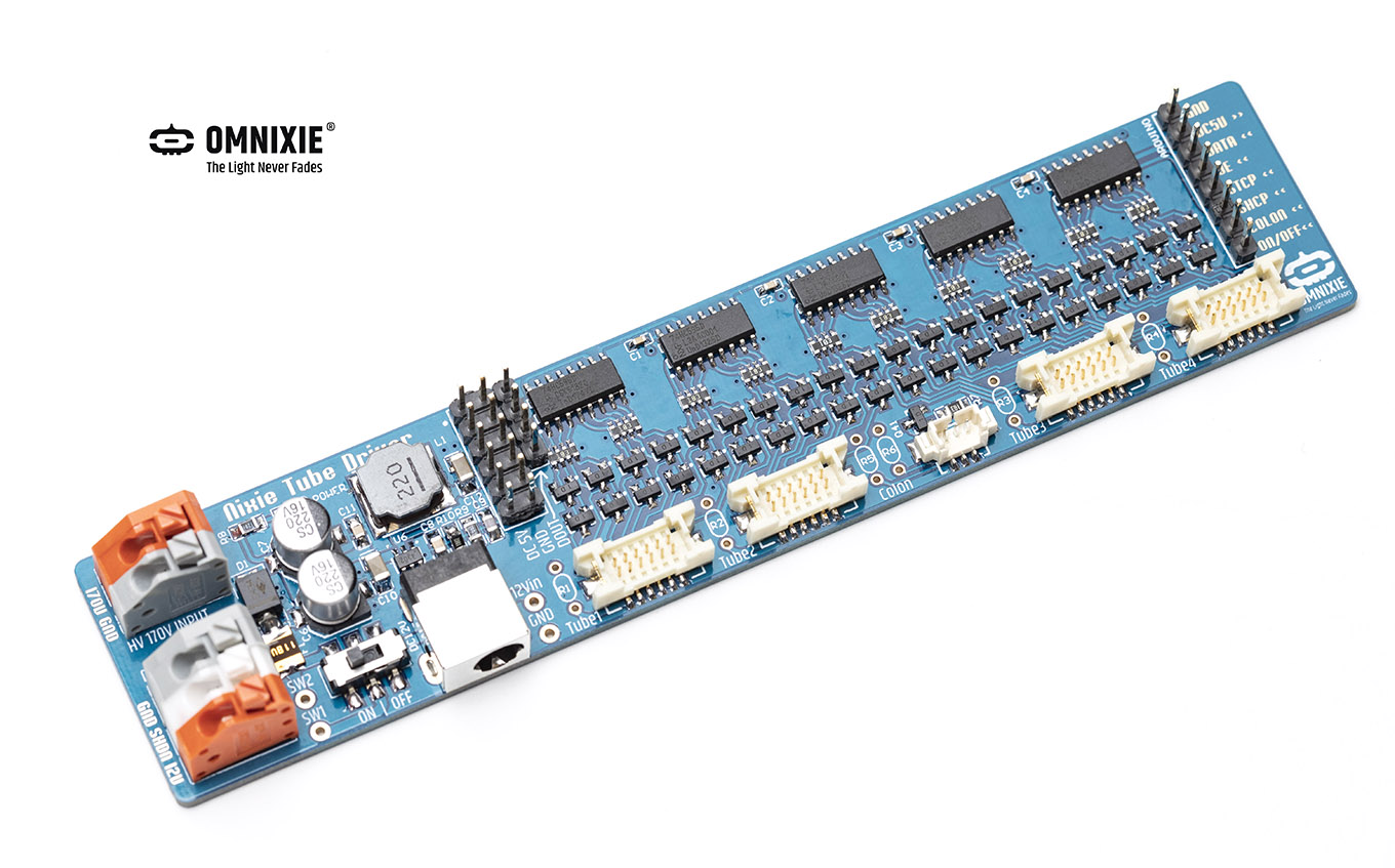
Nixie Tube Driver Board 4 (NTDB4)
This is the central documentation page for Nixie Tube Driver Board 4 (NTDB4) .
Dimensions
- Dimension: 140x30x15mm (L x W x H), or, 5.52×1.18×0.59 inches.
- 15mm is the thickness of the thickest component, the wire header.
Schmetics

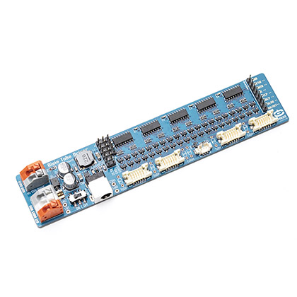
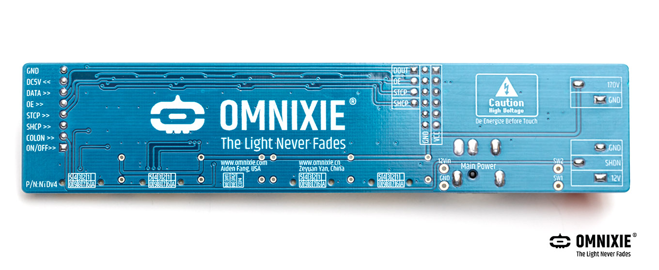
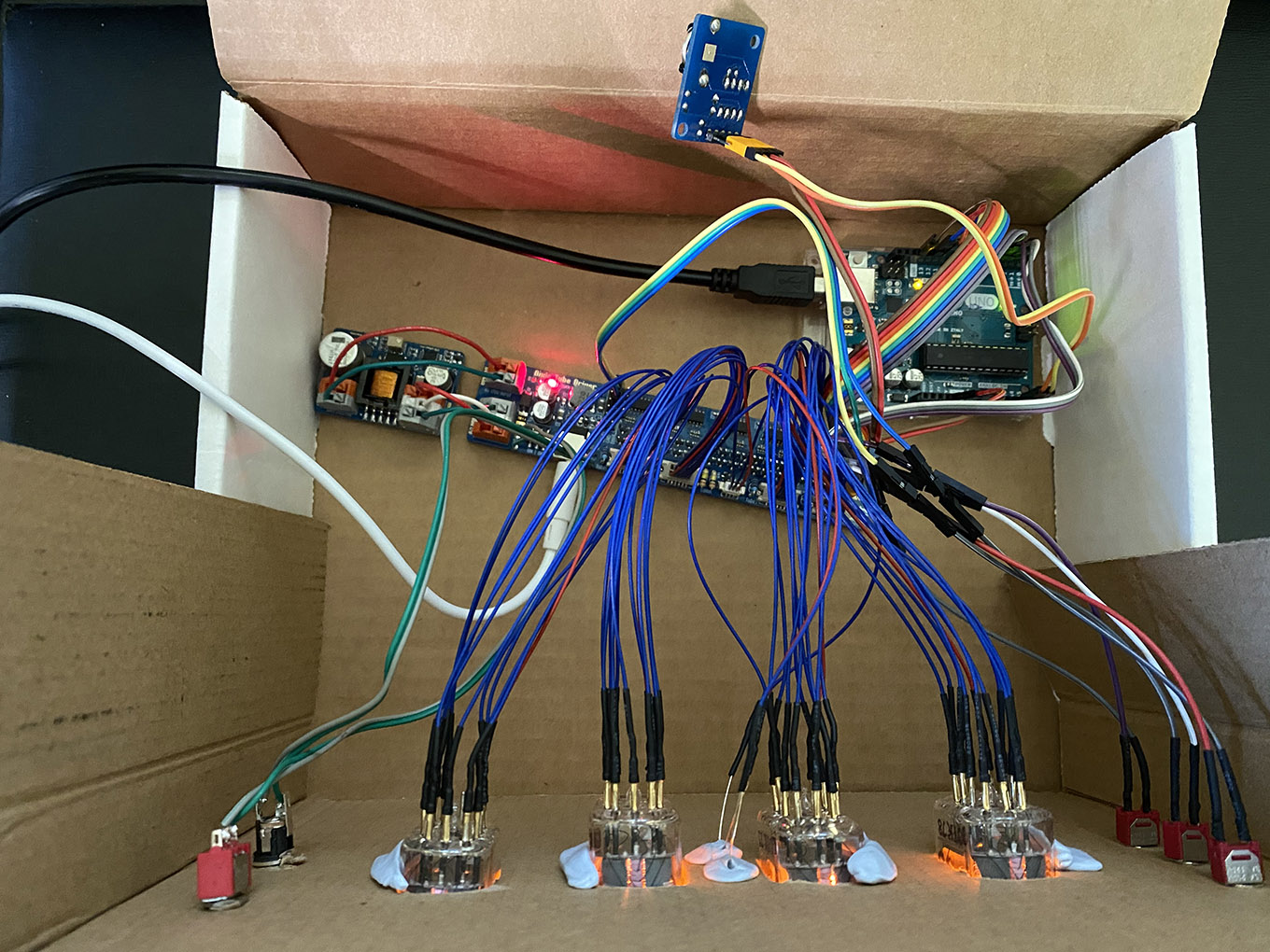
Photos


Purpose
The purpose of this Nixie Tube Driver Board is to simplify the making of a Nixie tube clock.
Connect an Arduino (or other MCU) board, a NCH6300HV and 4 nixie tubes to the Board, and that's pretty much it. Of course you'll need a few bells and whistles, like buttons, an RTC module, and some wires, but the heavy-lifting work has been done for you, all on the NTDB Board. And we also provide the Arduino example code to get you started. Isn't it easy enough? ^_^
Contents
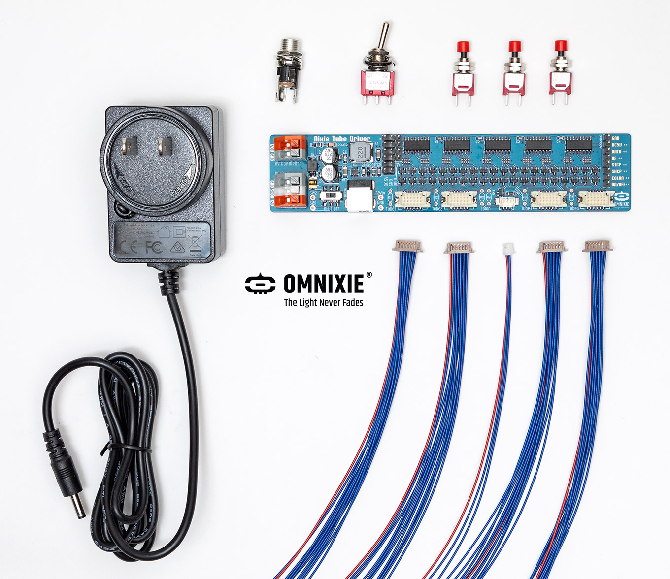
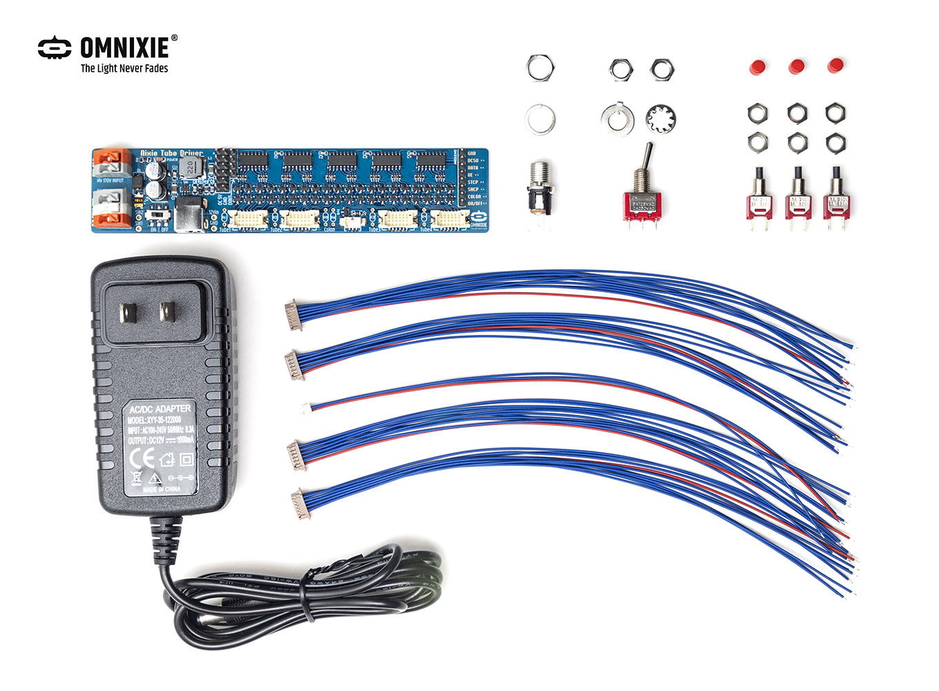
What the NTDB kit includes:
- 1x Nixie Tube Driver Board
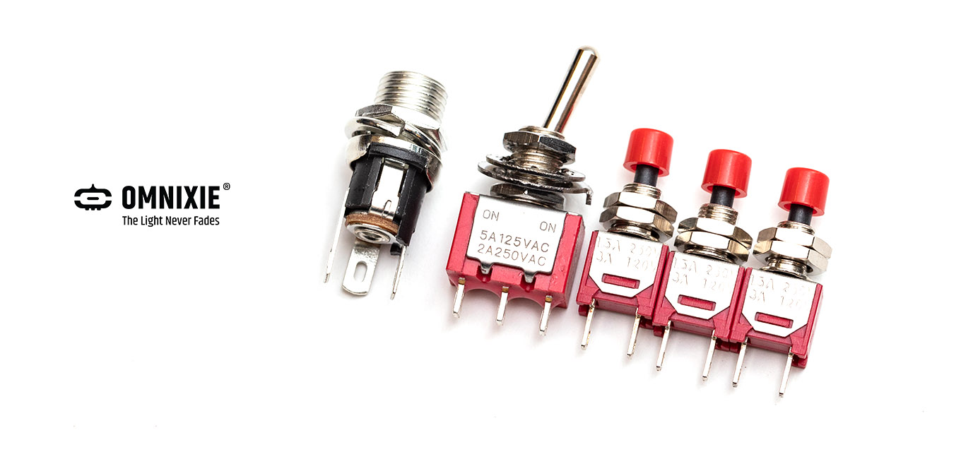
- 1x Power Switch (Panel-mount)
- 1x Power Socket (Panel-mount), with a split washer and a nut.
- 3x Tactile Buttons (Panel-mount)
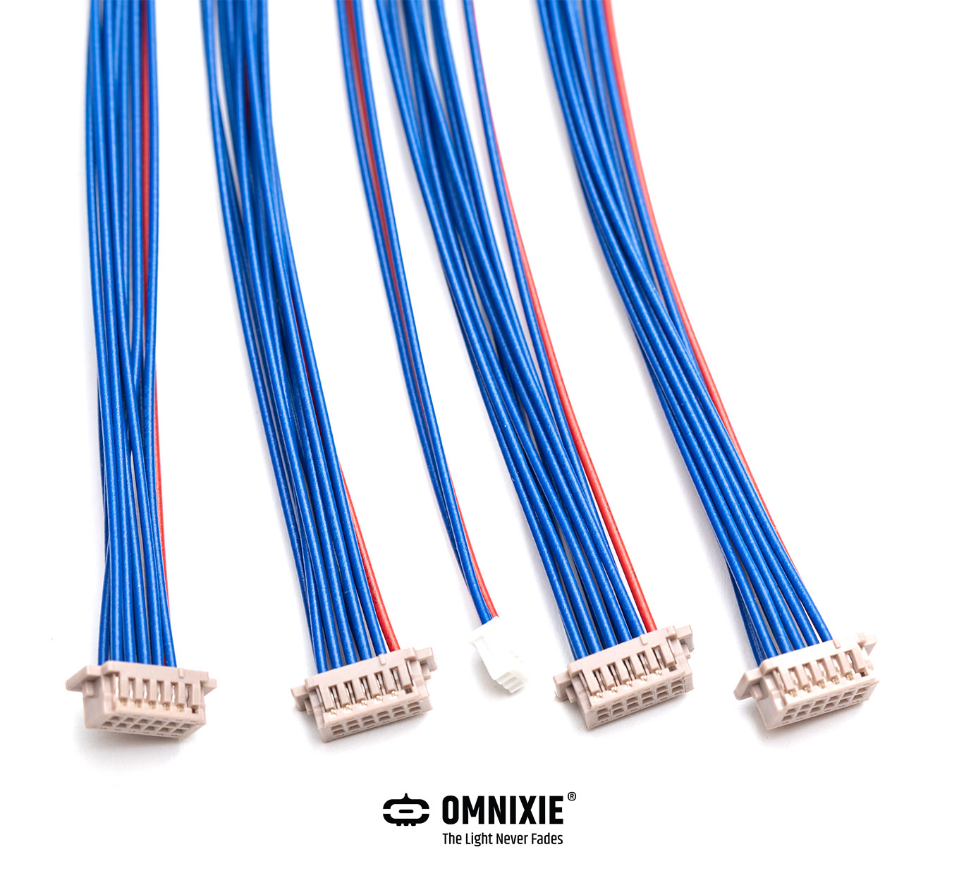
- 4x Board-to-Wire for Nixie Tubes (11 conductors, Red for the anode, and Blue for all cathodes)
- 1x Board-to-Wire for colons (3 conductors, Red for the anode, and Blue for 2 colons)
The resistors for anodes are left out intentionally, so that you can use those with proper resistance to match any nixie tubes of your choice. They are through-hole parts so basic soldering skill will suffice to install them.
In the connectors for tube connections, the pins are 0.05“ spaced apart within each connector. We choose these connectors to keep the board compact.
In addition to the panel-mount parts in the kit, there is already a switch and a power socket on board in fact. We thought you may like to make an enclosure to your own needs for your project, so we added the panel-mount ones in the kit, so that you can use them on your enclosure and hook them up using some wires. This way your project will look more like a finished product, doesn't it? ^_^
Arduino Library on GitHub
The Arduino library for the Nixie Tube Driver Board (NTDB4) was released on GitHub.
This Arduino library is designed to help you make your own nixie tube clocks with ease.
More tubes can be driven when multiple NTDB boards are connected in series.
The library provides two example projects for you to get started.
1) A minimal 4-Nixie-tube display.
2) A complete clock using 4 nixie tubes, 3 tactile buttons and 2 colon bulbs. See the chart below.
Flow Chart of the 4-Nixie-Tube Clock
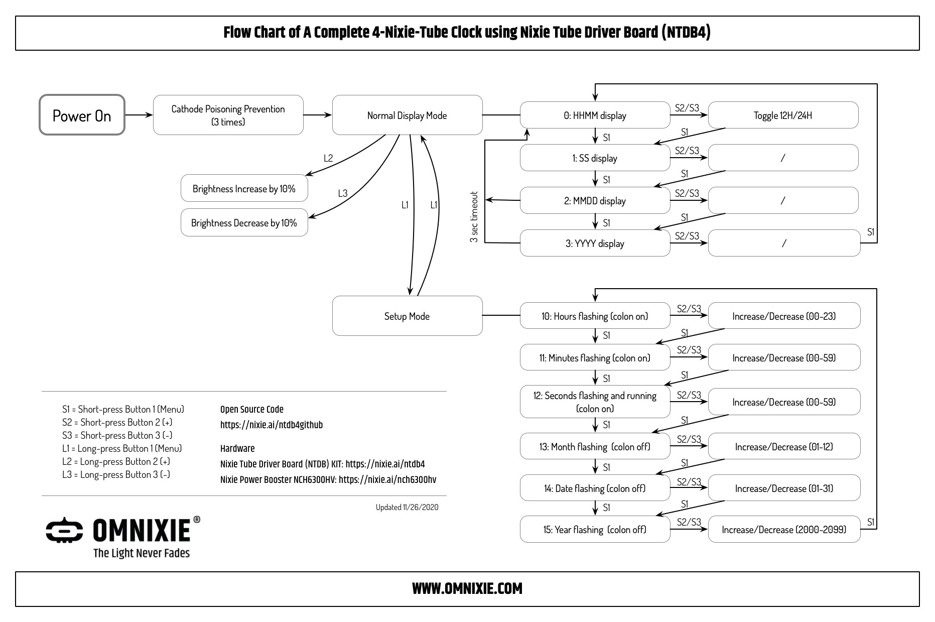
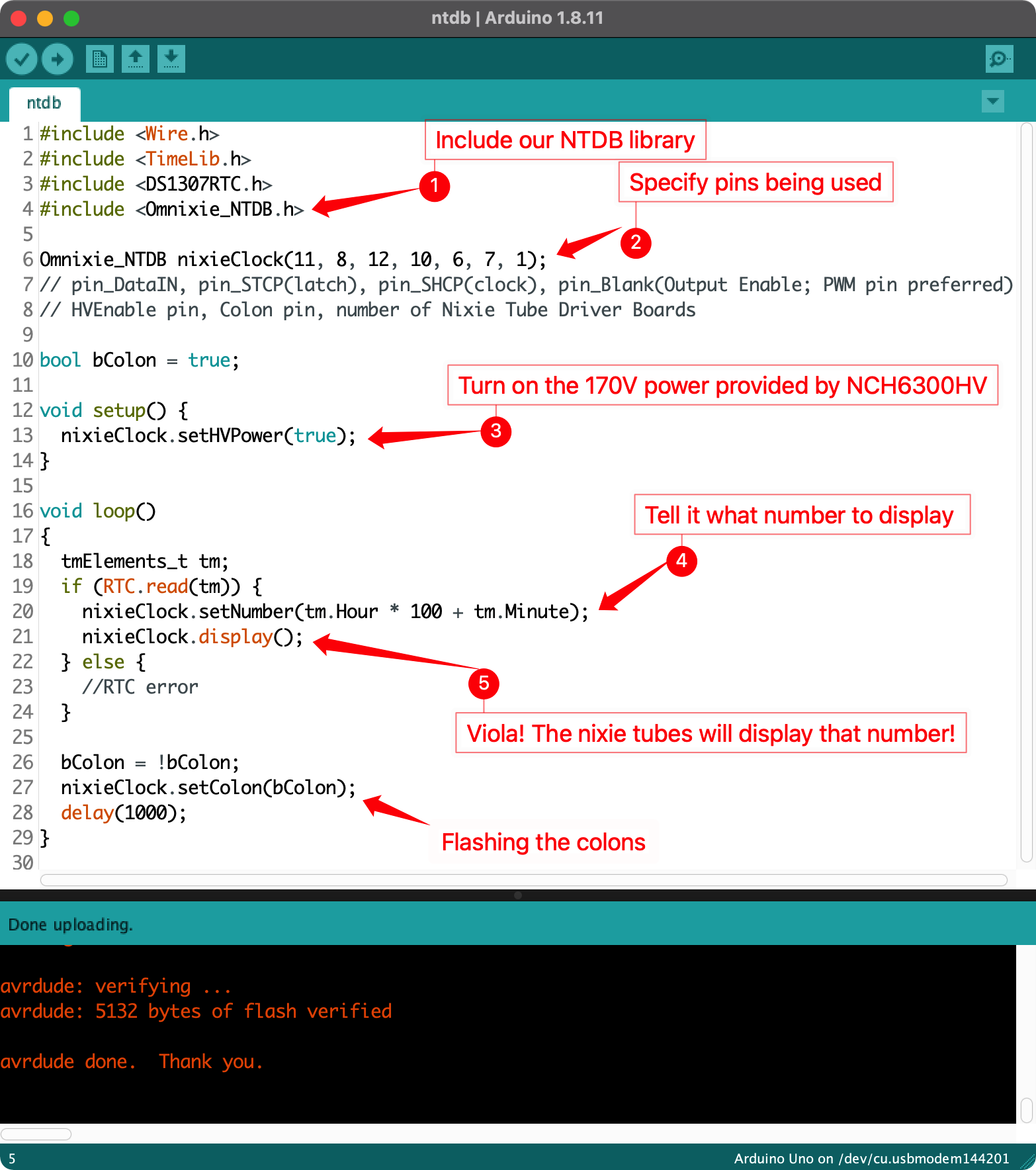
How to use the Arduino library
The code for a nixie clock involves 5 steps:
- Include our Omnixie_NTDB.h Arduino library
- Tell the code which pins are used.
- Turn on the 170V power, provided by NCH6300HV
- Specify what number for the tubes to display.
- Viola! It just works!
You may choose to flash the colons to make the clock complete, as shown in the image above.
Each board can drive 4 nixie tubes, two will drive 8 tubes, and so on. Since they are in series, they only take 4 I/Os on your Arduino board. So if you need to drive more tubes, simply add more NTDB boards in series.
Example Project 1: Minimal Tube Display
Step 1: Include the Omnixie_NTDB.h library
#include
Step 2: define how many NTDB boards in use
#define NTDB_count 1
Step 3:
Omnixie_NTDB nixieClock(11, 8, 12, 10, 6, 5, NTDB_count);
// pin_DataIN, pin_STCP(latch), pin_SHCP(clock), pin_Blank(Output Enable; PWM pin preferred),
// HVEnable pin, Colon pin, number of Nixie Tube Driver Boards
// PWM Pins on Arduino Uno: 3, 5, 6, 9, 10, 11; PWM FREQUENCY 490 Hz (pins 5 and 6: 980 Hz)
Step 4:
//turn on the high voltage provided by NCH6300HV
  nixieClock.setHVPower(true);

  // Brightness control, range 0x00(off) to 0xff(brightest).
  nixieClock.setBrightness(0xff);
  //turn on the tube display
  nixieClock.display();
Step 5:

for (int n = 0; n < 9999; n++) {
    //Specify what number to display, and which tubes to display
    nixieClock.setNumber(n, 0b1111);
    //Light up the tubes
    nixieClock.display();
    delay(10);
}
Here is the complete project.
/*
  Nixie Tube Driver Board (NTDB) 4-Nixie Tube Display Minimal Example

  This example demonstrates a minimal display using 4 nixie tubes.
  No colon bulbs. No buttons/controls. No clock.
  See aother example we provided for a complete clock.

  In order to make a complete clock, you will need:
  1) This KIT: https://nixie.ai/ntdb4
  2) 4x nixie tubes
  3) 1x NCH6300HV: https://nixie.ai/nch6300hv
  4) 1x Arduino Uno board
  5) 1x Real Time Clock module (DS1307, DS3231, etc)
  6) Some jumper wires


  Circuit:
  Connect the NTDB to Arduino Uno:
  --------------------------------
    NTDB        Arduino Pins
  --------------------------------
    GND         GND
    DC5V
    DATA        11
    OE          10
    STCP        8
    SHCP        12
    COLON       5 (Not In Use)
    ON/OFF      6 (HVEnable)
  --------------------------------
  Connect the 12V DC power to the NTDB board


  Nixie Tube Driver Board (NTDB) Arduino Library released at
  https://github.com/omnixie-electronics/Nixie-Tube-Driver-Board-Arduino-Library
  with short link: https://nixie.ai/ntdb4github

  First released in public domain on Thanksgiving day, 11/26/2020
  Library and example code created
  by Aiden Fang
  www.Omnixie.com

  NTDB board designed by Zeyuan, Yan
  www.Omnixie.cn

*/

#include


#define NTDB_count  1
// define how many NTDB boards in use

Omnixie_NTDB nixieClock(11, 8, 12, 10, 6, 5, NTDB_count);
// pin_DataIN, pin_STCP(latch), pin_SHCP(clock), pin_Blank(Output Enable; PWM pin preferred),
// HVEnable pin, Colon pin, number of Nixie Tube Driver Boards
// PWM Pins on Arduino Uno: 3, 5, 6, 9, 10, 11; PWM FREQUENCY 490 Hz (pins 5 and 6: 980 Hz)

void setup()
{
  //turn on the high voltage provided by NCH6300HV
  nixieClock.setHVPower(true);

  // Brightness control, range 0x00(off) to 0xff(brightest).
  nixieClock.setBrightness(0xff);
  //turn on the tube display
  nixieClock.display();

  //quickly loop through all digits to prevent cathode poisoning
  CathodePoisoningPrevention(3, 100);

}

void loop()
{
  for (int n = 0; n < 9999; n++) {
    //Specify what number to display, and which tubes to display
    nixieClock.setNumber(n, 0b1111);
    //Light up the tubes
    nixieClock.display();
    delay(10);
  }
}

void CathodePoisoningPrevention(unsigned int num, int msDelay) {
  if (num < 1) exit;
  for (byte n = 0; n < num; n++) {
    Serial.println("Running Cathode Poisoning Prevention ... ");
    for (byte i = 0; i < 10; i++) {
      nixieClock.setNumber(i * 1111, 0b1111);
      nixieClock.display();
      delay(msDelay);
    }
  }
  delay(1000);
}
Prototype

Example: Connection Scheme of TWO NTDB4 boards for (up to) 8 Nixie tubes
If you need to drive more than 4 nixie tubes, say, 6, you will need two NTDB4 boards.
Here is an example of how to connect two NTDB4 boards to make a nixie clock with up to 8 nixie tubes.
Components used in the scheme below:
- NTDB4 kits x2
- NCH6300HV (or NCH8200HV) high voltage power supply
- 12V power supply
- Arduino of your choice
- RTC module of your choice
- colon tubes if you choose to use them
- nixie tubes of your choice
- current limiting resistors for anodes of your nixie tubes
- wires of your choice

Beyond Nixie Clocks
Clock is merely an example. You can show numbers like stock prices, bitcoin prices, room temperature, game scores, YouTube subscribers, and on and on. With the combination of Arduino (or your own MCU), the possibility is unlimited. You can now add nixie display to any projects to show numbers!
We cannot wait to see what YOU can make with it.